This video was recorded using FactoryTalk Optix version 1.7. If you are using a different version of Optix, you may not be able to follow the steps exactly.
If you have worked with other HMI products like FactoryTalk View Studio or Studio 5000 View Designer, you are probably very used to a traditional HMI development workflow where you drop graphical elements on screens and manually arrange them into a nice layout.
In FactoryTalk Optix, you can manually lay out graphical objects on a screen, or you can use panels and containers to automatically lay out and arrange objects. Having objects automatically laid out is particularly useful for HMIs that need a responsive design to look good on devices of different shapes and sizes.
In this tutorial, I’ll introduce you to the different panels and containers that are available to layout graphical objects in FactoryTalk Optix and explain how each one works. If you’re new to FactoryTalk Optix, this should be considered required reading because it will help you streamline how you build your HMI screens.
Let’s start by talking about windows.
Get the project from this tutorial on GitHub:
https://github.com/kencbourke/Optix-PanelsAndContainers
In FactoryTalk Optix, a window is the entry point and parent container for an HMI application.
FactoryTalk Optix is a single-window application so when you navigate between screens, you are actually changing the content that is displayed in the window, you are not navigating to a different window.
By default, most FactoryTalk projects contain a MainWindow object, which is a window.
.png)
A project can have more than one window to provide different entry points for an application. You could, for example, have a window that is loaded when the application runs on an Optix Panel and a different window that is loaded when the application is accessed through a web browser.
Screens are displayed in a window and contain graphical objects. An HMI application is typically made up of multiple screens with a mechanism to navigate between them.
In FactoryTalk Optix, you can add a screen to a project by right-clicking on the Screens folder and selecting New > Screen.
.png)
By default, a screen’s Horizontal and Vertical Alignment properties are set to Stretch. This means that a screen will take up the full size of the parent container.
A panel is a container that can be used to group multiple objects together. Panels are very important when it comes to creating reusable objects in FactoryTalk Optix.
You can add a panel to a screen by right-clicking on the screen and selecting New > Containers > Panel.
.png)
Unlike screens, panels are aligned to the top left of their parent containers and have a fixed size by default.
.png)
As well as foundational containers like windows, screens, and panels, FactoryTalk Optix contains some layout containers. These are containers that help to organize the graphical objects that they contain.
A horizontal layout arranges the graphical objects inside it horizontally.
To demonstrate this behavior, I add a new screen to my project, add a horizontal layout to the new screen, and set its Horizontal and Vertical Alignment properties to Stretch.
.png)
Inside the horizontal layout, I add four rectangles with a black background and a length and width of 200 pixels. These rectangles are automatically laid out horizontally in the container.
.png)
In the properties for the horizontal layout, I can use the Horizontal and Vertical Gap properties to create space between the rectangles.
.png)
I can also use the Wrap property to automatically create a new row when the content in the container overflows.
.png)
Finally, I can use the Content Alignment property to control how the content is aligned in the container.
.png)
A vertical layout is just like a horizontal layout but lays out content on a vertical axis.
.png)
A grid layout lets you lay out content based on a configured grid pattern, which is made up of columns and rows.
To configure the structure of the grid, you can select the pencil icon beside the Columns and Rows properties to open the editor.
.png)
Within the editor, you can specify the number of columns and rows as well as their sizes. Sizes can be specified in relative frame units, which is basically the percent of the total size of the container, or pixels.
.png)
As you add graphical objects to the grid, they are assigned to the cells that have been created by the columns and rows.
.png)
The scale layout scales objects inside the layout with the container. This is very useful for applications that will run on a non-fixed size window like a web browser to ensure that the content of an application is always visible.
When you are setting up a scale layout, you can set the Fill Mode property to Fit, which maintains the aspect ratio of the content, or Stretch, which ignores the aspect ratio of the content and fills the container.
In my example, I have added a circle to a scale container and increased the size. When I set the Fill Mode to Fit, the circle remains a circle regardless of how wide I make the container:
.png)
If I set the Fill Mode to Stretch, then the circle is stretched out to an oval shape to fill as much of the scale layout as possible.
.png)
You can also specify if text inside of the layout should be scaled using the Font Scaling property.
In this tutorial, you have seen the most important containers that are available in FactoryTalk Optix to organize graphical objects on your screens. This idea of automatically laying out graphical objects is very important in HMI applications that will run on devices of different sizes or in re-sizable windows like a web browser.
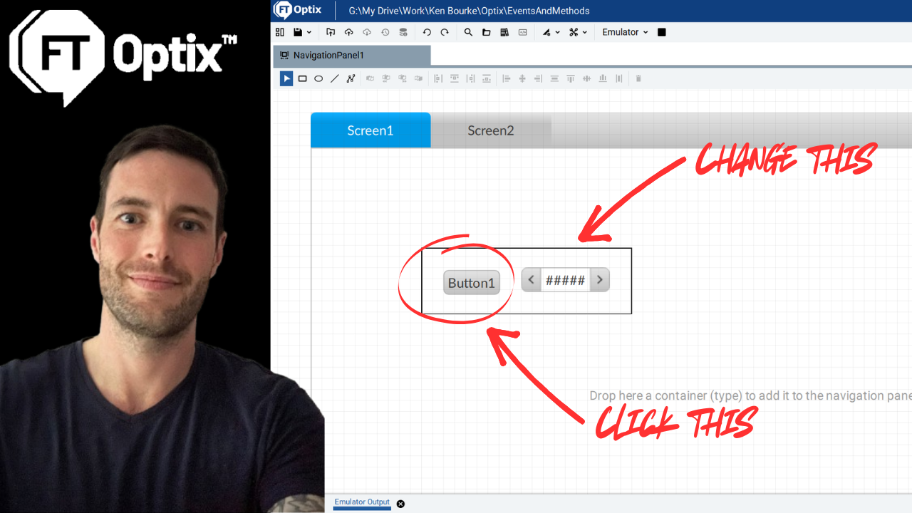
If you have followed along with the tutorial, you will have a project that contains several screens. Obviously, we need a way to navigate between screens and display their content in the Main Window. In my next tutorial, I will explain how to set up navigation in FactoryTalk Optix using Panel Loader and Navigation Panel containers.
See you there.
Get new content delivered straight to your inbox:
.png)