
If you're going to work with PLCs, the one skill you can't skip is reading and writing Ladder Logic. It's the most common PLC programming language, and a lot of the logic you'll run into in the field is written in it.
In this post, I'll cover the basics you need to be comfortable reading and writing Ladder Logic code.
By the end of this post, you'll know:
Let's get started.
Ladder Logic, also known as Ladder Diagram, is the most common programming language for PLCs. It's a graphical language that's designed to be easy for electricians and technicians to read, write, and monitor.
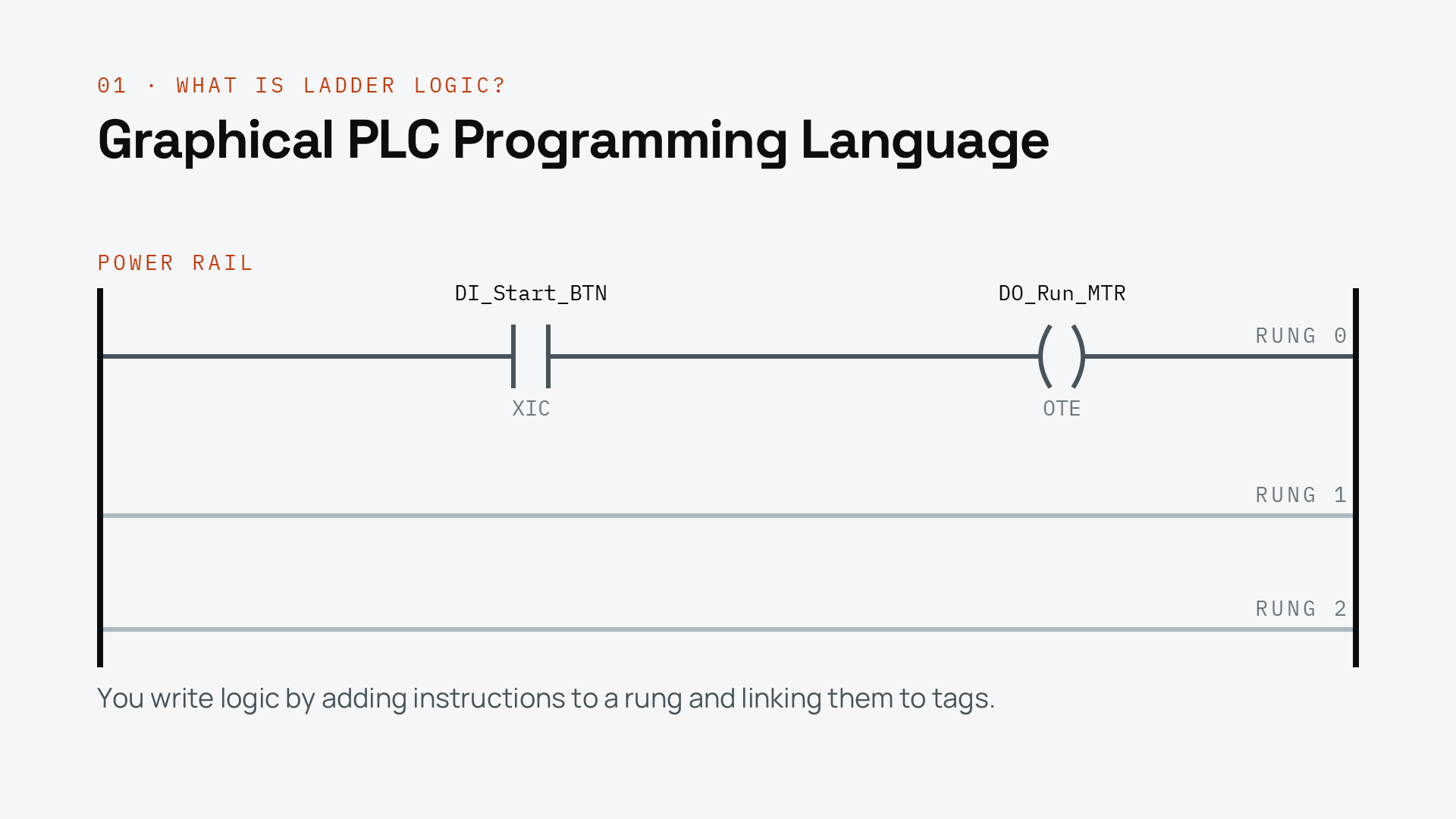
Each line of code is called a rung, because it looks like a rung on a physical ladder. You write logic by adding instructions to a rung and linking those instructions to tags.
We'll talk about tags in more detail in another post - for now, just think of them as the physical inputs and outputs of the PLC.
There are two basic categories of instructions: input instructions and output instructions.
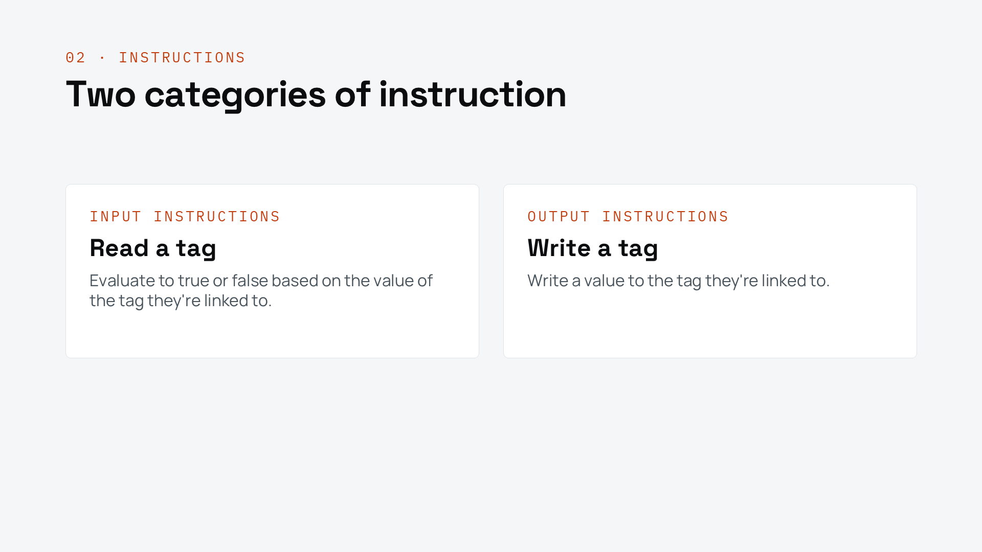
Output instructions write a value to a tag, and they always sit on the right-hand side of the rung.
Shown here is an Output Energize instruction, which is linked to the tag DO_Run_MTR. This is a digital output on the PLC that runs a motor for a conveyor.
You'll often hear Output Energize referred to by its mnemonic, OTE.
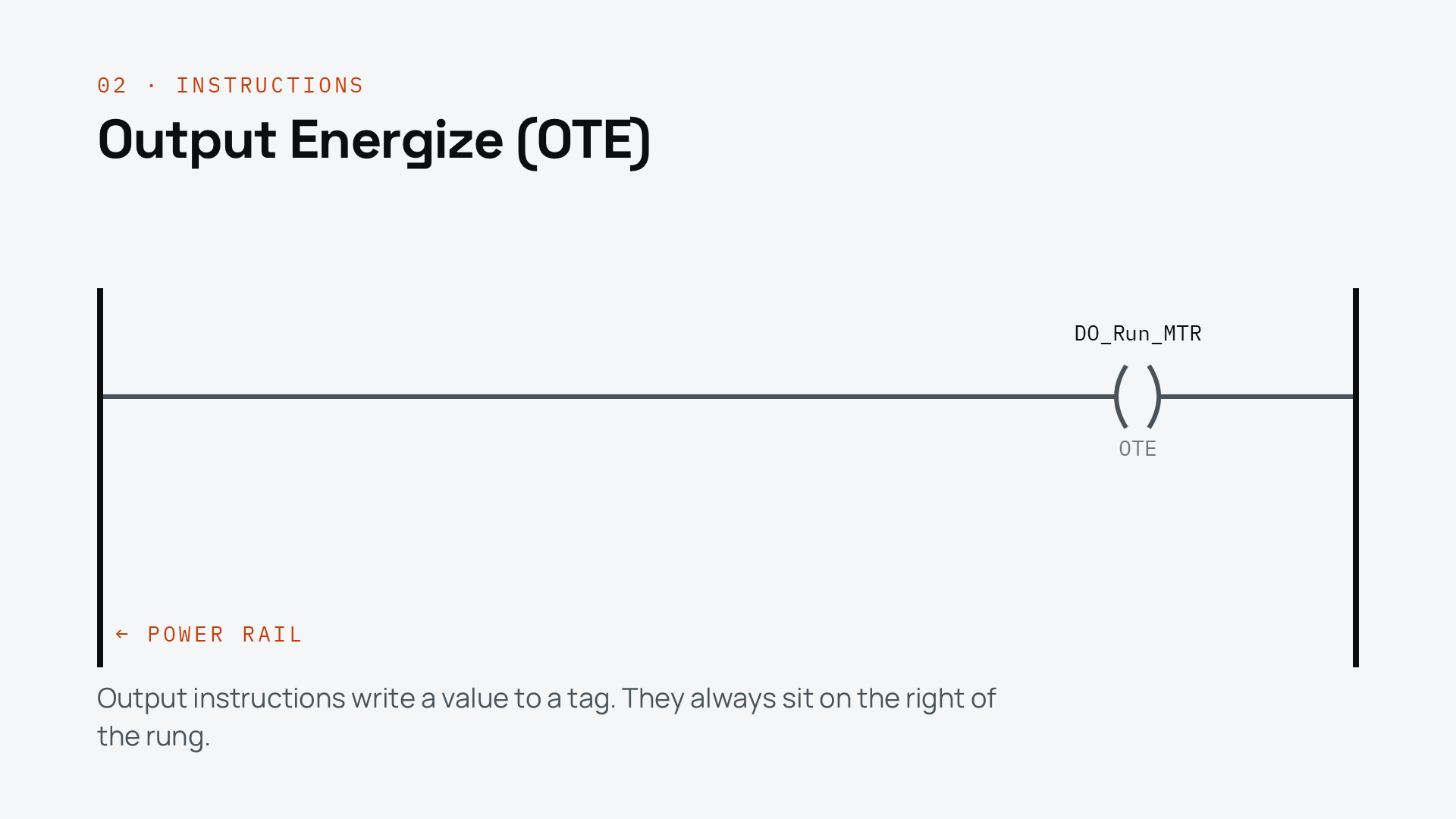
To understand how this executes, look at the vertical bar on the left of the rung. That's called the power rail.
When there's a continuous path from the power rail to an output instruction, that instruction evaluates to true. Another way to say this is that the rung-in condition for the instruction is true.
An OTE writes the value 1 to its linked tag when it evaluates to true, and writes 0 when it doesn't. When we're talking about digital inputs and outputs, the values 1 and 0 are often referred to as true and false.
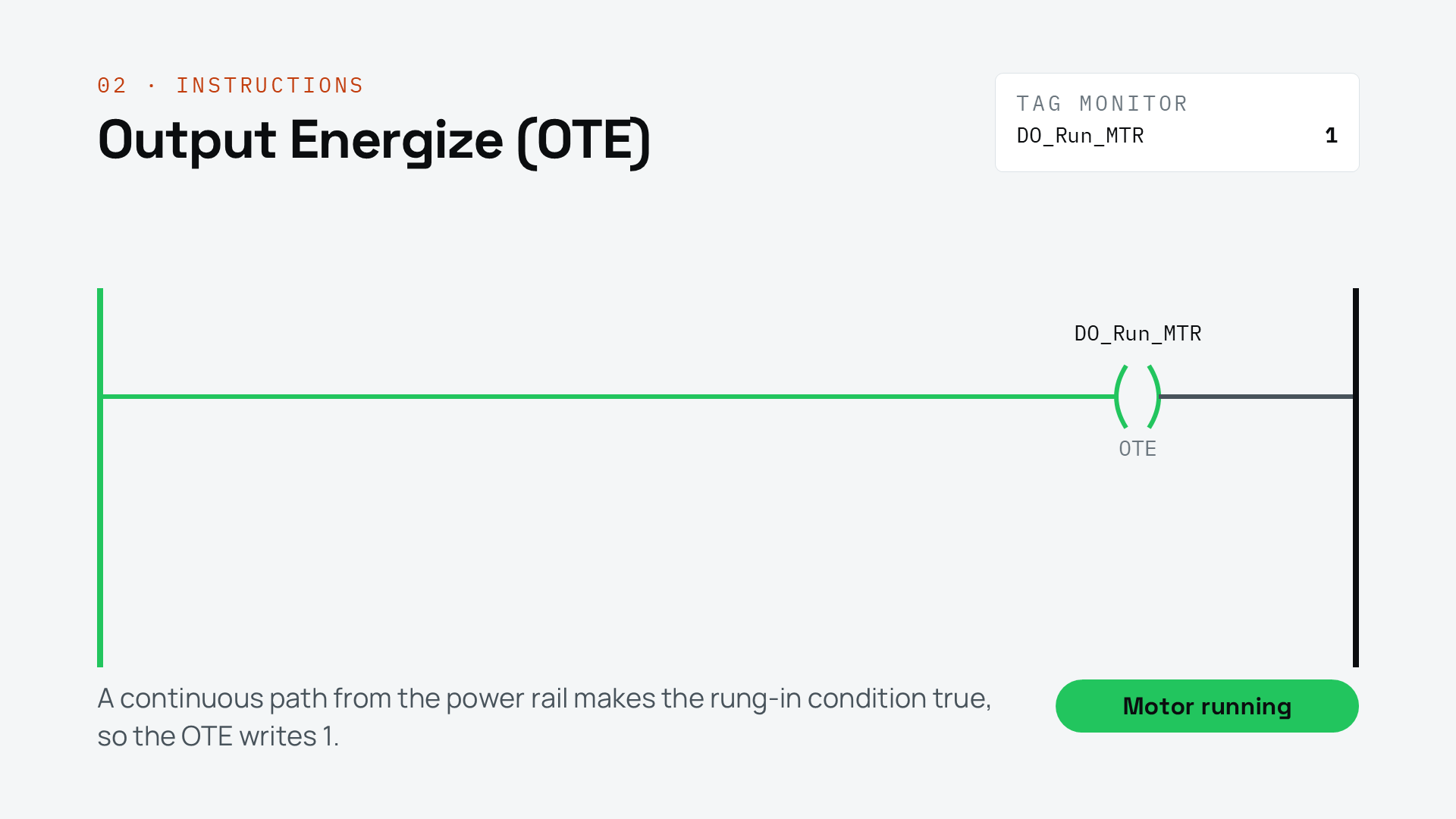
On this rung there's nothing between the power rail and the OTE, so there's always a continuous path. Every time the PLC scans this rung, it writes 1 to DO_Run_MTR, and the motor runs.
This logic isn't very useful. Let's see how we can control the output using input instructions.
Input instructions read the value of a tag and evaluate to true or false based on that value.
Here I've added an Examine If Closed, or XIC, instruction to the rung and linked it to the tag DI_Start_BTN, which is the input from a start button.
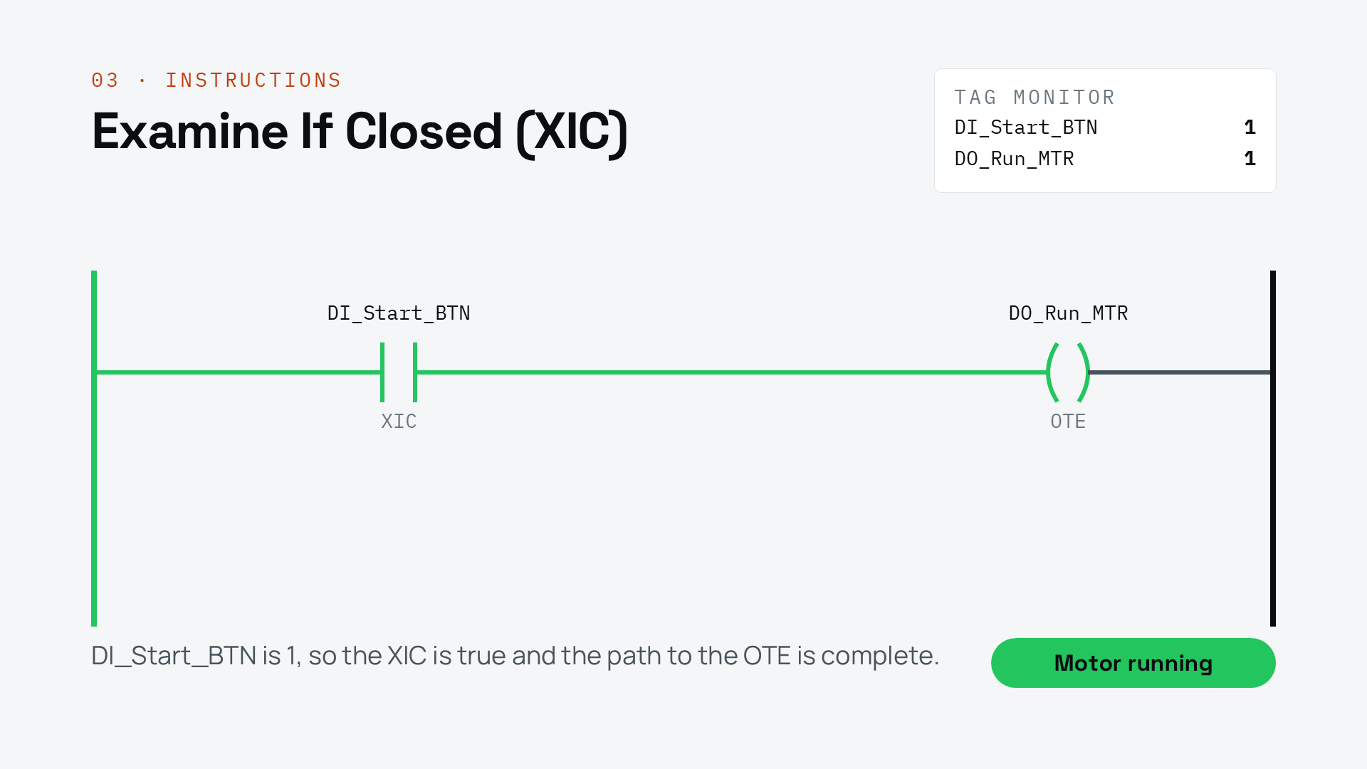
When DI_Start_BTN is true, the XIC evaluates to true. That creates a continuous path from the power rail to the OTE, and the motor runs.
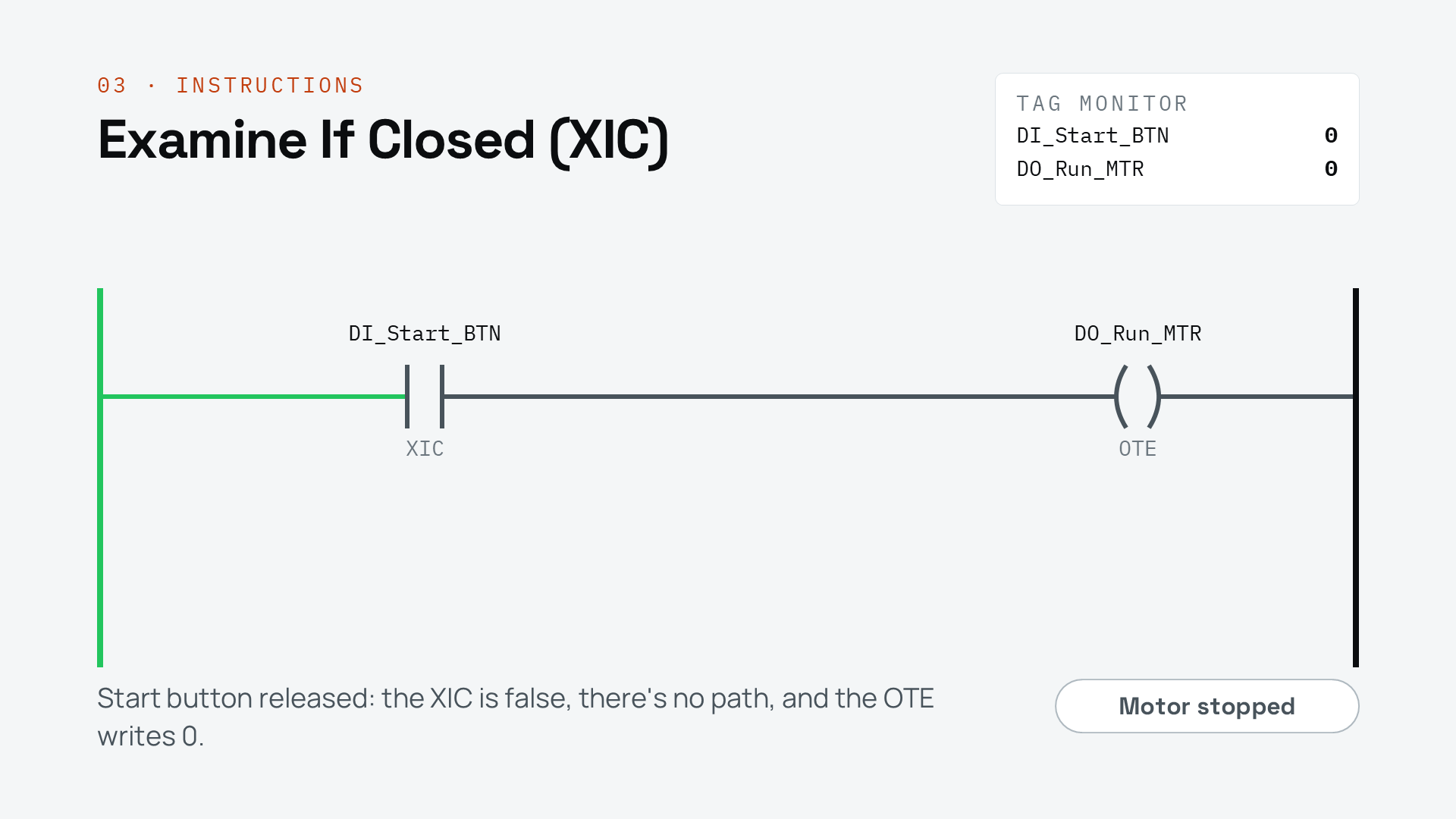
When the start button isn't pressed, the XIC evaluates to false and breaks the continuous path to the OTE, so the motor doesn't run.
If you read this rung out loud, it says: if the start button is pressed, run the motor.
You can build more complex logic by combining instructions on a rung.
When you put instructions in series, one after the other, you get AND logic, where every condition has to be true for the output to turn on.
Here I've added an Examine If Open instruction, or XIO, and linked it to the tag DI_Sensor, which is the input from a sensor. An XIO is the exact opposite of an XIC. It evaluates to true when its tag is false, and to false when its tag is true.
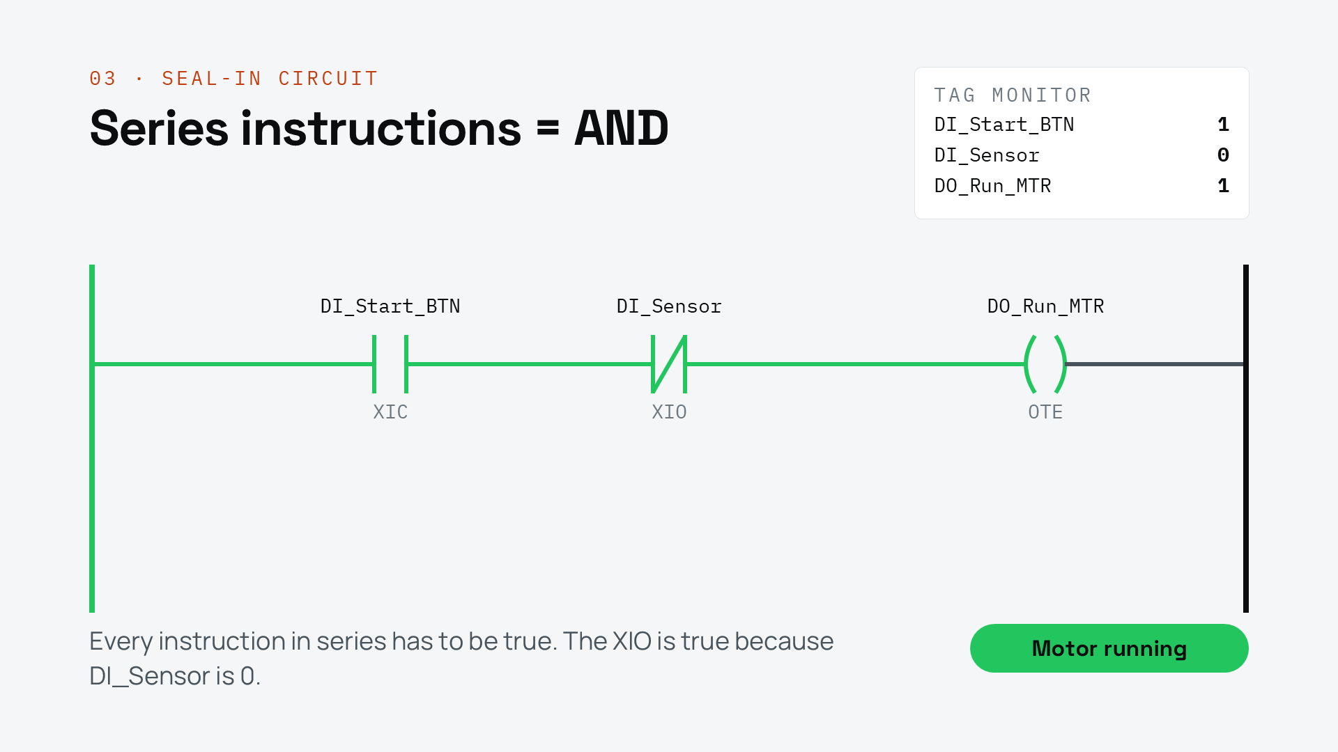
Now the motor runs if the start button is pressed AND the sensor isn't triggered.
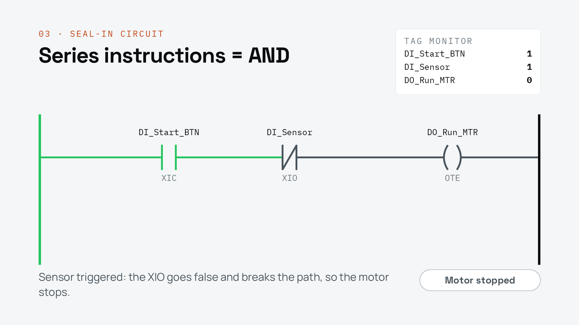
If the start button isn't pressed, or the sensor is triggered, the motor doesn't run.
You can also build OR logic by putting instructions in parallel, and you do that with a branch. A branch gives the rung an alternative path to the output.
Here I've added a branch around the start button, and on that branch I've put an XIC linked to DO_Run_MTR, the motor output itself.

When the start button is pressed and the sensor isn't triggered, the motor runs, just like before.
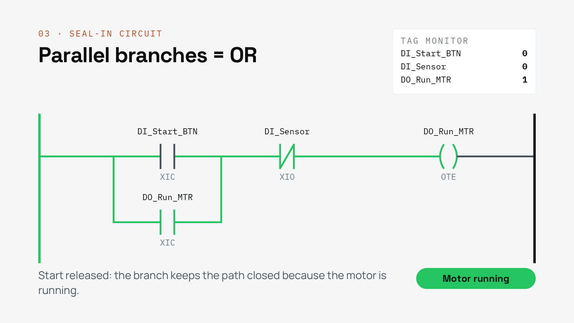
But now, when I release the start button, the motor keeps running. That's because the motor output is true, so the XIC on the branch is true, and that keeps a continuous path to the OTE.
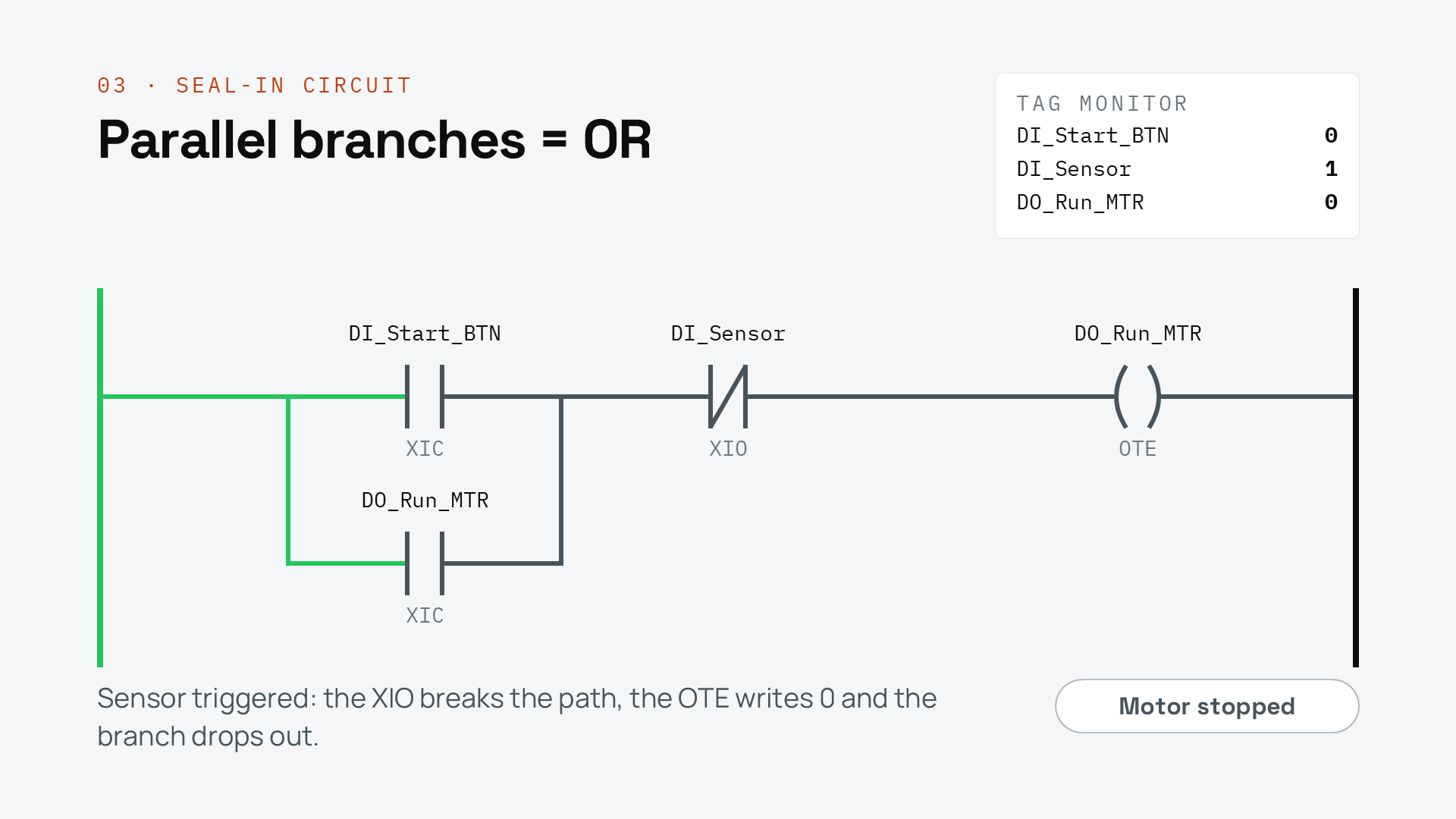
The motor keeps running until the sensor is triggered and breaks the path.
This is a common design pattern called a seal-in circuit. It gets that name because the branch seals the output in: once it turns on, it holds itself on.
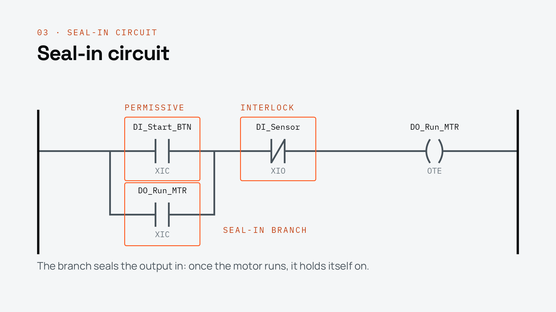
A seal-in circuit is built from two kinds of conditions: permissives and interlocks.
Permissives are conditions that have to be true for a process to start, but don't have to stay true for it to keep running. In this example, the start button is a permissive.
Interlocks are conditions that have to be true for the process to keep running. If an interlock drops out, the process stops. Here the sensor is an interlock, because the motor stops as soon as the sensor is triggered.
Finally, the seal-in branch is a branch that goes around the permissives and refers to the seal-in circuit's output. This branch is what keeps the output on even when the permissives are false.
Seal-In Circuits are commonly used because they are non-retentive. This is because XIC and XIO instructions have special pre-scan logic that sets them to false before the rung is scanned for the first time.
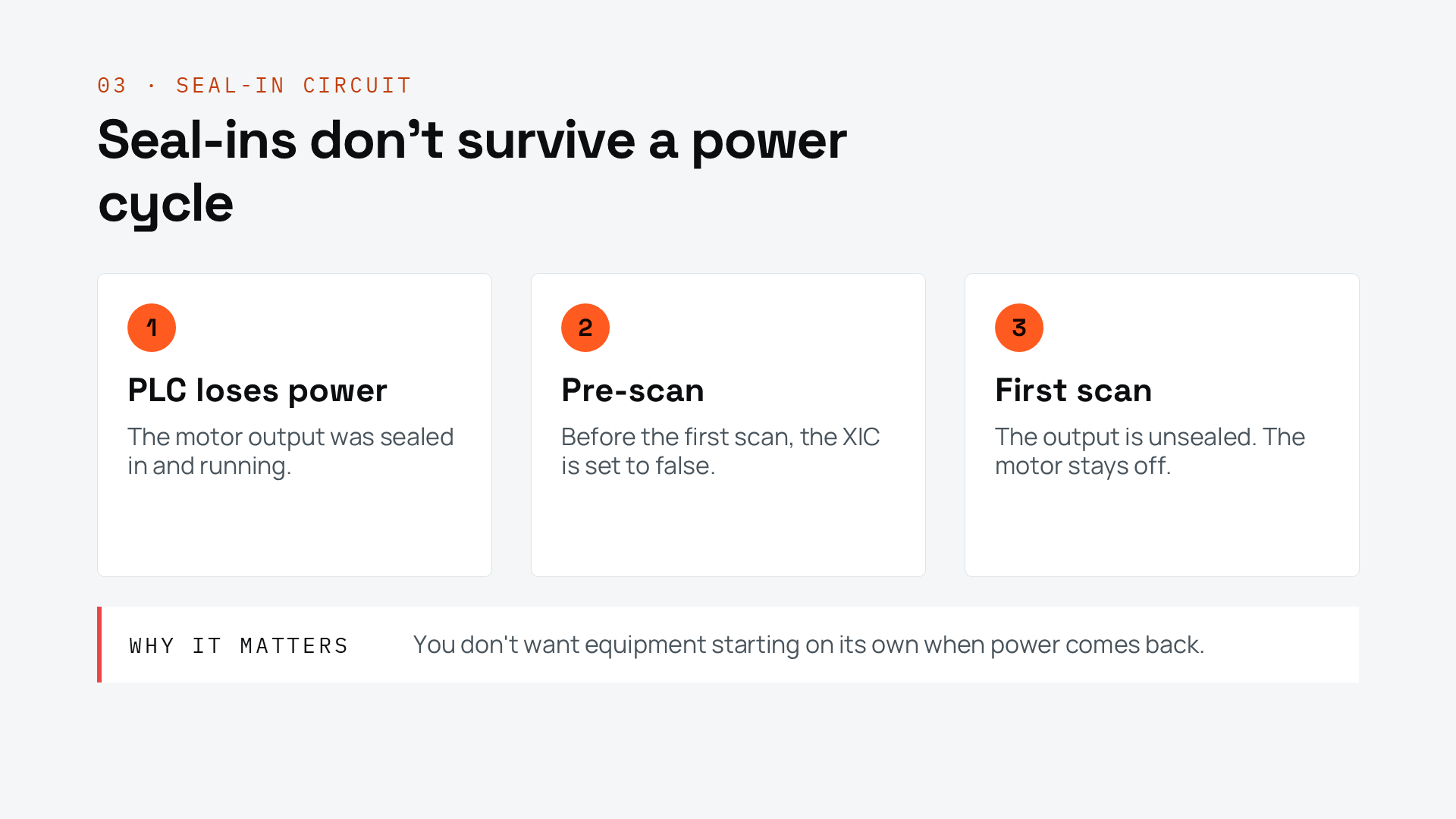
This is a really important detail for logic that controls motors - if the PLC loses power, you don't want motors to start without warning when it is turned back on.
So that's the basics of Ladder Logic. Now you know how rungs work, how the most common instructions behave, how to build AND and OR logic, and how a seal-in circuit works.
Get new content delivered straight to your inbox: